This is my first 4 bit adder built with nothing more than relays.
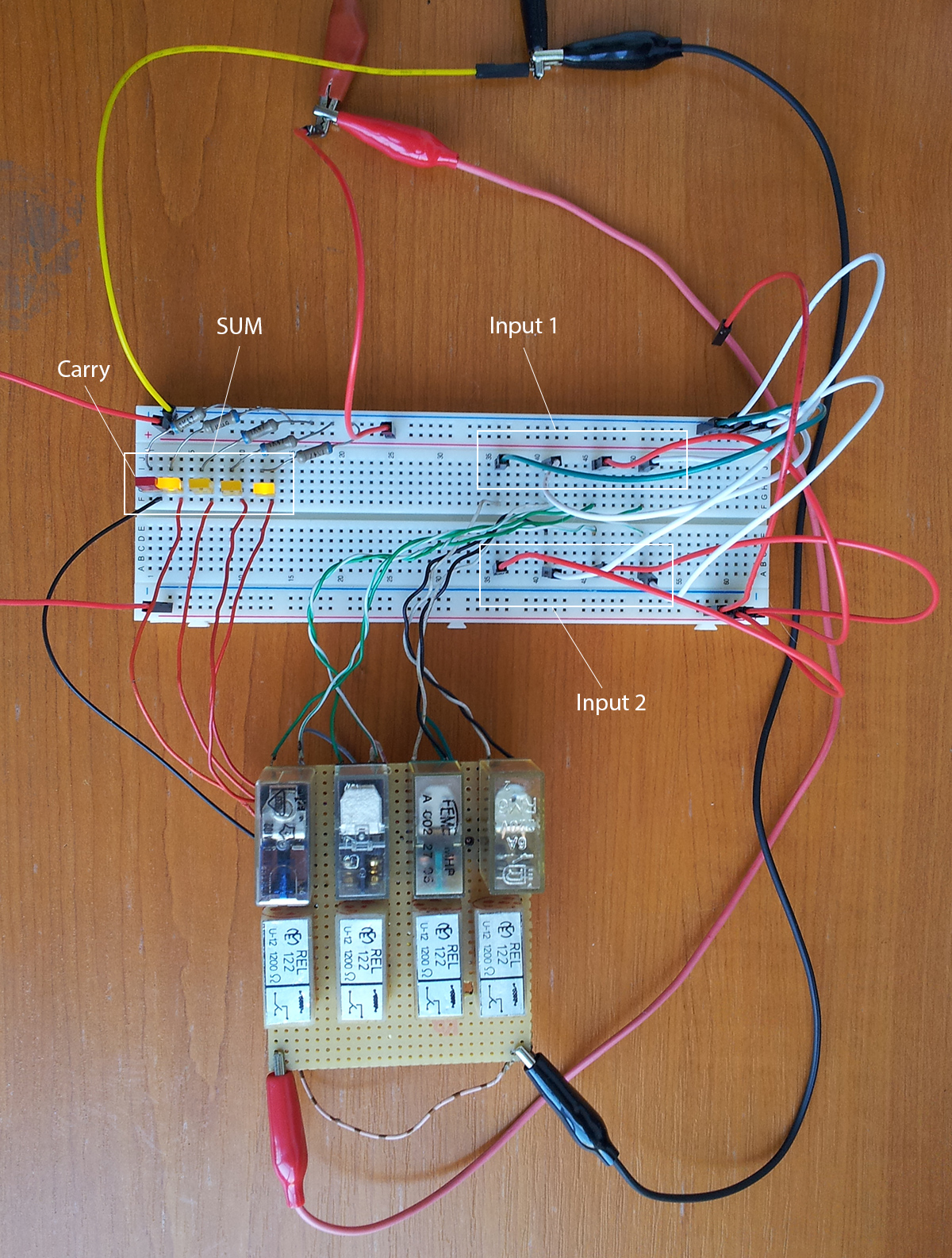
The forest of wires on the right are used to set the input values (in the picture Input1 = 0100 (4 in base 10) and Input2 = 0101 (5 in base 10)), and the LEDs on the left are used as output indicators for the SUM (in this picture 1001 (9 in base 10)).
do you have a schematic for your 4 bit relay computer you could e-mail me?
Thanks
John
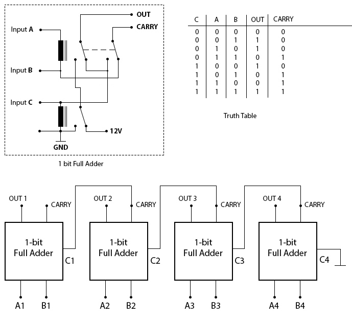
I’ve included a schematic in the above article.
Great work.
Thank you for breaking it down like this on how it wired. ive been looking on how to build a 4 bit relay adder.