From all the existing tubes, for sure the most interesting ones are the indicator tubes. From the 1930’s when they were invented, they captivated the eyes with the greenish shimmering light, thus the “Magic Eye” term appeared. The magic eye tubes are just small CRT derivations, usually they also have a triode built-in, as an amplifier.
I had two EM84 laying around for some time ( EM84 are cheap and easy to find, mostly on eBay ), and as I was planning to start an all tube stereo amplifier, it made perfect sense to use magic eye tubes as vu-meters, although EM84 can hardly be called a magic eye, it is more a “magic stripe”.

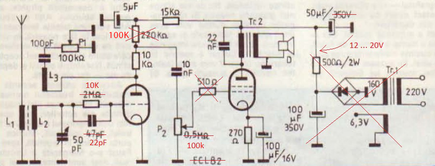
I started from the circuit in the right picture, and tweaked the values of the anode and grid resistor for a full range of indication.
If the bar is at full range and not moving, try to adjust the 5M potentiometer connected to the grid.
The grid voltage varies between 0 to -22V ( yes, the grid is negative ).
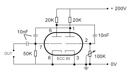
If this circuit is used with a tube amplifier, the “IN” connection in the picture is connected to the anode of the last tube in the amplifier. For an input from another signal source, a preamp stage with a BC171 transistor ( a MOSFET would be a better choice for high input impedance ), is needed.
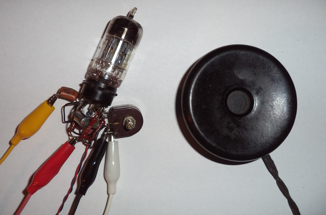
Here is a picture with the tube and circuit.

If you don’t have a transformer that outputs 200+ volts, you can get this voltage by building a small DC-DC converter.
To check if the tube is working, first feed the tube with the correct voltages like is described here.