electro

Arduino Uno 6 digit clock

I had an arduino uno and some modules laying around for some time, and finally I decided to make it a weekend project and put it to useful work, by building a clock that could display the time in HH:MM:SS format.

Digging the web for inspiration, I found many examples that involved an extra 74HC595 shift register and a BCD to 7-segment decoder and a RTC (real time clock) module for greater accuracy.

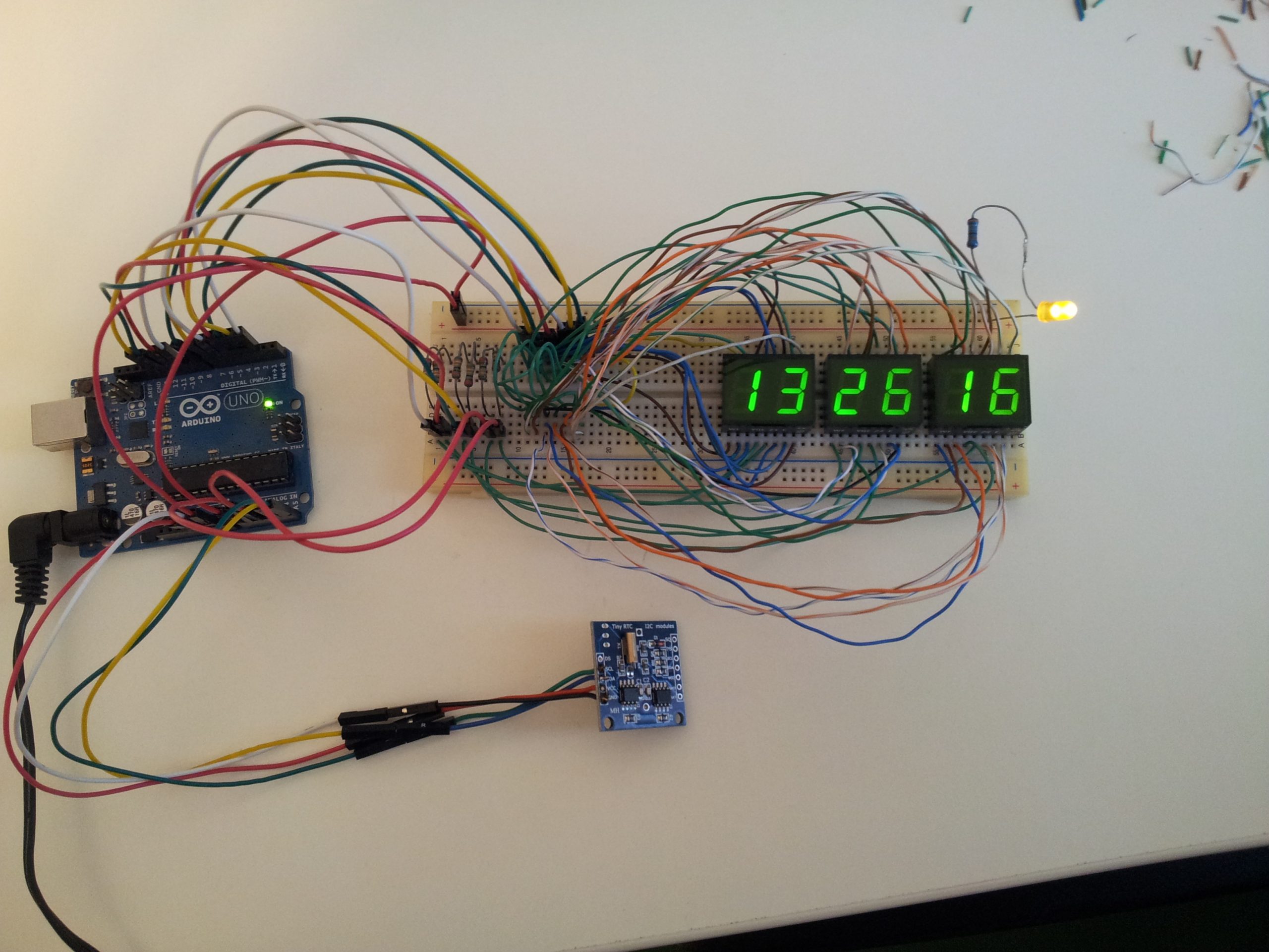
I had a DS1307RTC module, the problem was that the only 7-segment decoder I found in the junkbox was a CD4511 which can only drive common-cathode dispays, and the displays I had where VQE24E common-anode.
I could’ve added transistors, but for 6 digits there would’ve been a lot of transistors and resistors.

In the end I found about SevSeg.h library, that makes it posibble to drive both common-cathode as well as common-anode displays easily, directly from arduino.

I took inspiration from here for the code: https://electronics-project-hub.com/arduino-7-segment-display-clock-with-and-without-rtc/

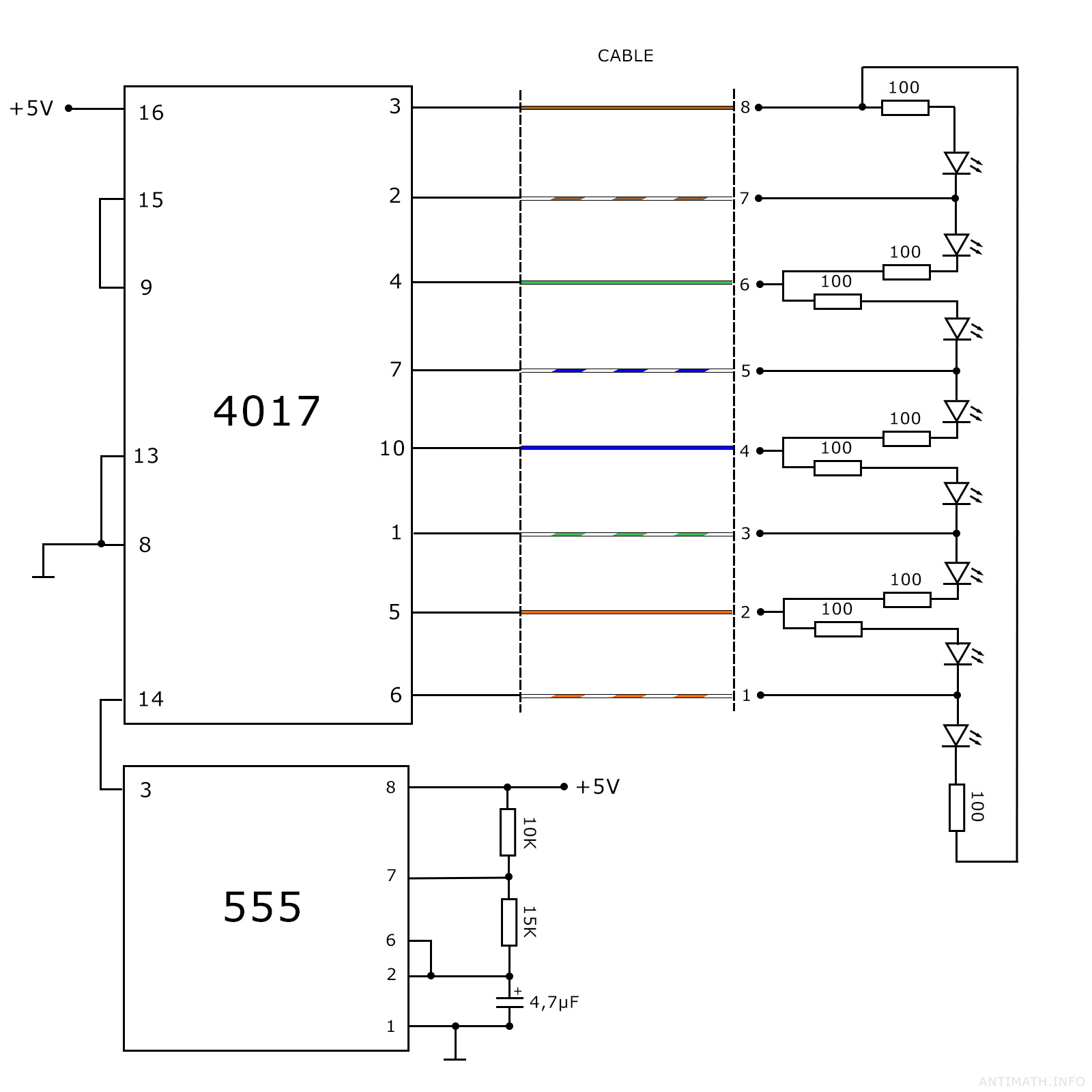
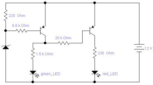
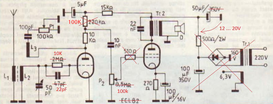
Below is my modified code and circuit diagram:

#include "SevSeg.h"
#include <Wire.h>
#include <TimeLib.h>
#include <DS1307RTC.h>
SevSeg Display;
const int ledPin =  A0;
unsigned long timeDisplay;
unsigned long currentMillis;
unsigned int Hour;
int ledState = LOW;
unsigned long previousMillis = 0;
const long interval = 500;
void setup()
{
  pinMode(ledPin, OUTPUT);
  byte numDigits = 6;
  byte digitPins[] = {10, 11, 12, 13, A1, A2};
  byte segmentPins[] = {2, 3, 4, 5, 6, 7, 8, 9};
  bool resistorsOnSegments = false; // false = resistors are on digit pins
  bool updateWithDelaysIn = true;
  byte hardwareConfig = COMMON_ANODE;
  Display.begin(hardwareConfig, numDigits, digitPins, segmentPins, resistorsOnSegments);
  Display.setBrightness(100);
}
void loop()
{
  unsigned long currentMillis = millis();
  if (currentMillis - previousMillis >= interval)
  {
    previousMillis = currentMillis;
    if (ledState == LOW)
    {
      ledState = HIGH;
    }
    else
    {
      ledState = LOW;
    }
    digitalWrite(ledPin, ledState);
  }
  tmElements_t tm;
  if (RTC.read(tm))
  {
    Hour = tm.Hour;
    if (tm.Hour == 0)
    {
      Hour = 24;
    }

    timeDisplay = (Hour * 100 + tm.Minute) * 100L + tm.Second;
  }
  else {
    timeDisplay = 888888; // error
  }
  Display.setNumber(timeDisplay);
  Display.refreshDisplay();
}

In the end I didn’t use the blinking seconds LED, but left the option there.

To set the time on the DS1307 RTC, I followed the instructions in the link above.

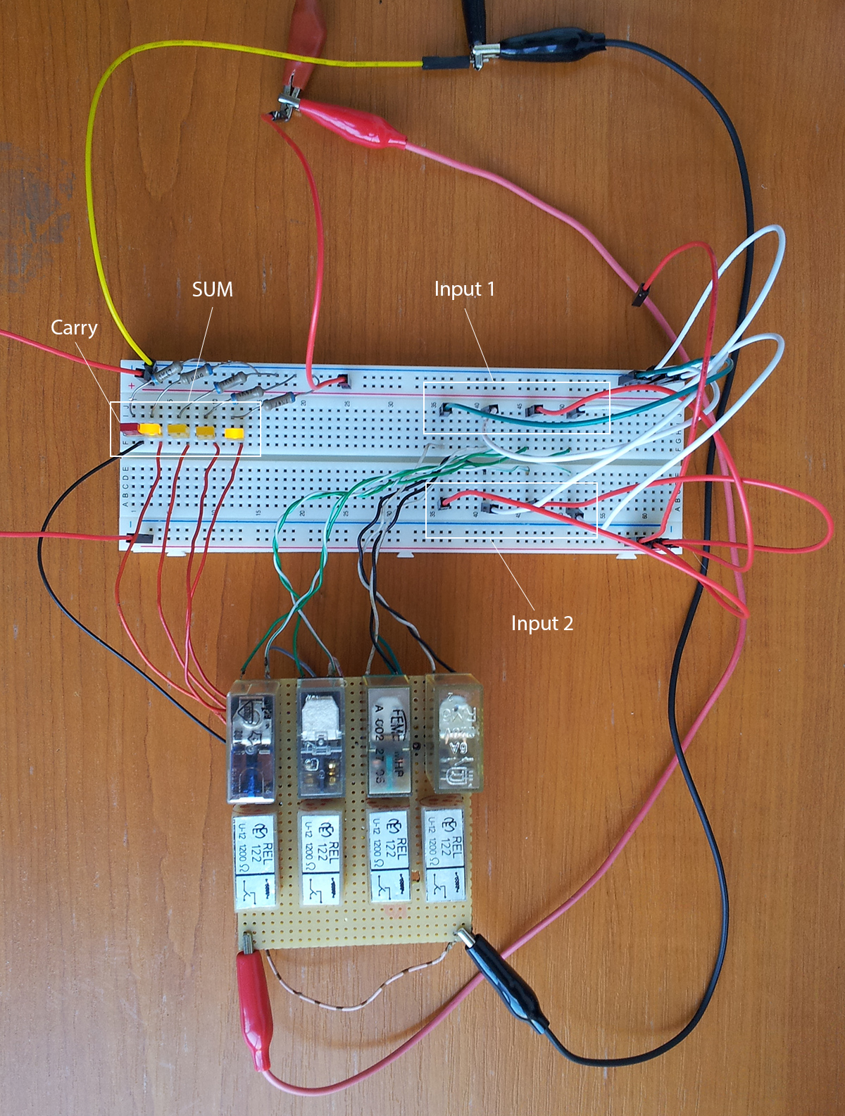
On the breadboard there are anode resistors, but I ended up not using them. These displays needed some higher current to lit up well during the day.

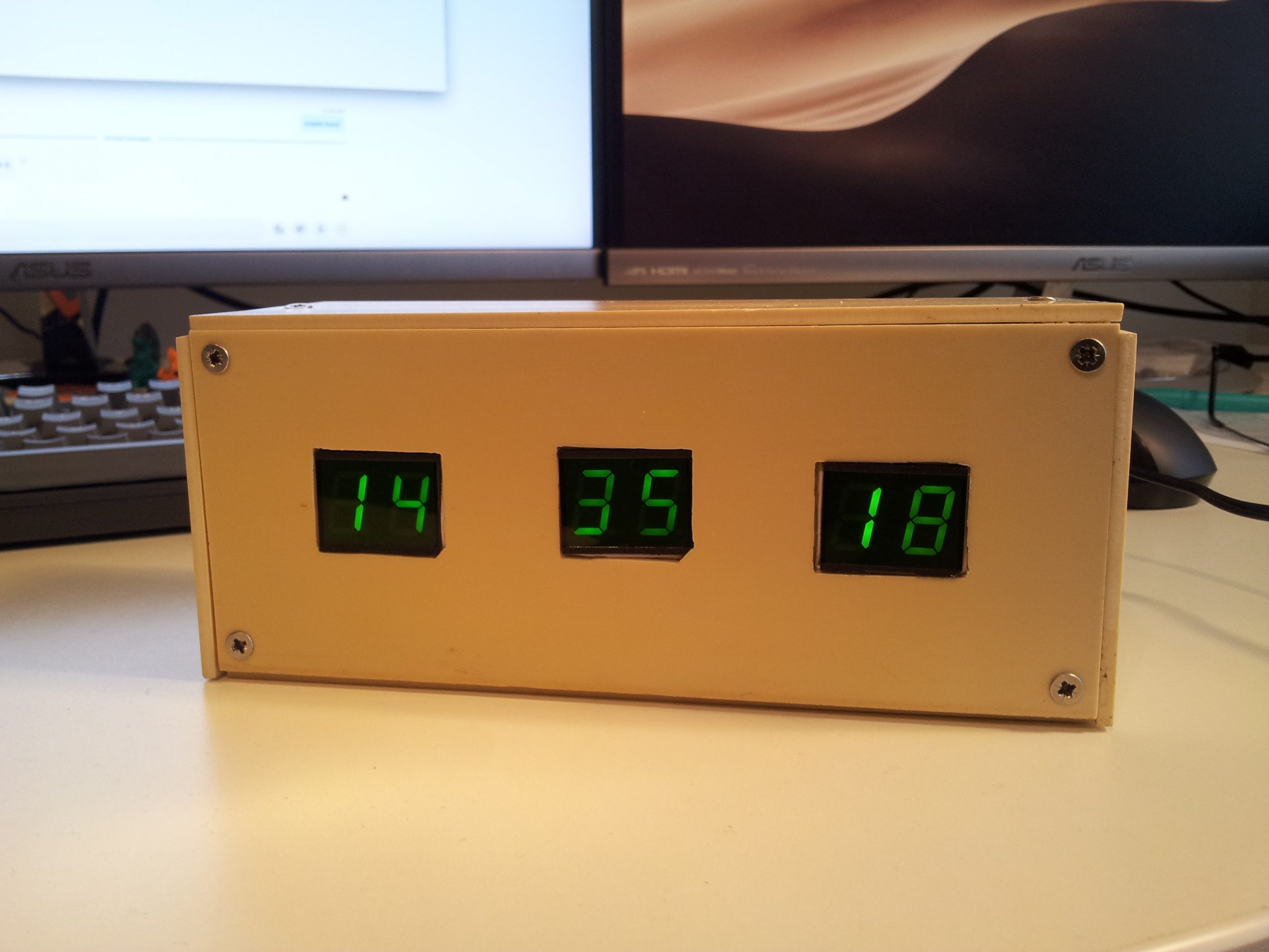
I know the box isn’t the prettiest one, but at least it’s a box :)

Later edit (12 june 2020):
It seems that the DS1307 RTC (at leas the one I have) is not so “real”… the clock gained over 60 seconds in almost three weeks. Not very accurate for a clock crystal.

Novus 4510 Mathematician

A friend gave me this National Semiconductor Novus 4510 Mathematician scientific calculator made in 1976, and I couldn’t resist taking it apart.

It is an interesting calculator, simply by being a Reverse Polish notation (RPN) machine.

On the inside, the hardware it’s pretty simple, with only two IC’s and a 9-digit 7-segment bubble LED display, mounted on a single side fiber glass PCB. The keyboard seems pretty robust and it’s fixed to the front part of the case, while the PCB it’s mounted on the back part of the case, connected through a flat flex cable.

IC1: MM5760N – 24 pin DIP, Slide Rule Processor
IC2: DS8864N – 22 pin DIP, Segment-Digit Parallel-Input Display Driver

novus-4510-pi

novus-4510-inside

novus-4510-back

Network cable tester

Build a network cable tester with just two cheap integrated circuits and a few parts from the ‘junkbox’.
This cable tester, tests all the 8 wires in a network cable in one move, if one of the 8 LEDs does not lit up, it means that the wire corresponding to that LED is faulty.

You need:

  • 1 x 4017 decade counter,
  • 1 x 555 timer,
  • 8 x LEDs,
  • 2 x 8P8C modular connector (RJ45),
  • 8 x 100Ω resistor,
  • 1 x 10KΩ resistor,
  • 1 x 15KΩ resistor,
  • 1 x 4,7µF capacitor.

network-tester

The yellow LED has no special significance, I only had 7 green LEDs.

A good ideea would be that every LED have the color of the corresponding wire, and maybe a switch for the T568A and T568B standards.

Threshold voltmeter

threshold-voltmeter

This is not an actual voltmeter, it just “detects” if the input voltage is below or above a certain threshold. The threshold voltage is the breakdown voltage of a Zener diode.

I have seen this in a magazine described as an rudimentary car battery voltage indicator, recently I have used it as a protection circuit, just replaced the red LED with a relay, acting like a switch (closed when the voltage is under the threshold value and open if the voltage is grater).

4 bit relay computer

This is my first 4 bit adder built with nothing more than relays.

4bit-adder-schematic

4bit-adder

The forest of wires on the right are used to set the input values (in the picture Input1 = 0100 (4 in base 10) and Input2 = 0101 (5 in base 10)), and the LEDs on the left are used as output indicators for the SUM (in this picture 1001 (9 in base 10)).

Square wave generator with 7400 series chip

This is a simple and useful oscillator, built, using  just a 7400 chip ( 4 NAND gates ) and very few other components.

7400-square-wave
7400-square-wave-pcb
square-wave-signal

ECC83 tone generator

The circuit is basically a multivibrator constructed around a double triode ( I used ECC83 ), and oscillates around 1KHz.

ECC83 multivibrator

At the output I’ve connected a 2000 Ohm telephone loudspeaker, but with a transformer, a 4 Ohm speaker could be used as well.

The frequency can be adjusted from the 100K variable resistor.

The ECC83 works well even at low voltage ( ~20V ).

ecc83-tone-genarator-circuitecc83-tone-genarator-circuit-darkwaveform

1bit half adder with one relay

With just one double relay, you can make an adder capable of performing 1bit additions:

0 + 0 = 0
0 + 1 = 1
1 + 0 = 1
1 + 1 = 0 ( with Carry = 1 )

1bit-half-adder

The circuit design isn’t mine, I found it with a quick google search.

1bit-relay-adder-1
1bit-relay-adder-2

1bit-half-adder-full-detail

This is the complete schematic of the above circuit.

DIY high power USB car charger

For some time I felt the need of an USB charger in my car, but all the commercial ones I’ve seen haven’t convinced me they are reliable. So I proposed myself to build one which would have to be “virtually indestructible”, stable and safe for the devices I connect to it.

I remembered that I had a LM340KC-5.0 (5V positive regulator in TO-3 case), laying around somewhere, and told myself that this is perfect for the job. After I looked over the datasheet, I did a test circuit, and it performed perfectly.

I bought a telephone outlet to use it as a case, and I mounted two USB receptacles (which I dismembered from an old computer motherboard) instead of the telephone jack, and the LM340 on top of the case.

The USB pins configuration you can find on Wikipedia.

I have also added a green LED to know if is working.

Have fun.

How to test a bipolar transistor

This post refers to how to test a bipolar junction transistor (BJT) with an ohmmeter.

A bipolar transistor has two PN junctions; a PN junction basically behaves as a simple diode. Bipolar transistors come in two types, NPN and PNP, based on how the base of the transistor is doped.

A simple method to see if the transistor is good ( presuming you have just an ohmmeter ), is to use the ohmmeter to test each of the two junctions.

Note: You can use any type of ohmmeter ( analogical or digital )

Set your ohmmeter on the X1 domain, and:

Step1: Connect the red probe to the base(B) of the transistor and the black probe to the emitter(E)

Now we test the PN junction between the base and emitter ( BE ).

Red probe to base and black to emitter.

Step2: Connect the red probe to the base(B) of the transistor and the black probe to the collector(E)
Now we test the PN junction between the base and collector ( BC ).

Red probe to base black to collector.

If you get readings ( higher then 0Ω ) in both cases, then the junctions are good, and because the red probe was connected to the base, means that the transistor is NPN type. ( You should NOT get any readings ( Ω ) with the black probe connected to the base. )

Step3: If you didn’t get readings at Step1 and 2, then move the black probe to base(B), and repeat Step1 and 2

If you get readings, as in steps 1 and 2, but with the black probe connected to the base, and no readings at all with the red probe connected to the base, that means your transistor is also good, but is of PNP type.

Summary:

  • Red probe connected to base, and readings with the black probe connected to both emitter and collector ( one at the time ) => transistor is GOOD and is NPN.
  • Black probe connected to base, and readings with the red probe connected to both emitter and collector ( one at the time ) => transistor is GOOD and is PNP.
  • Both cases above, but no readings ( Ω )  or short-circuit ( 0Ω ), means the transistor is fried.

ECC81 tube radio

I’ve seen a lot of circuits with tubes at low voltage ( max 20V ), so I wanted to experiment with one too,… and what could be more fun to play with than a radio.

I started from a short-wave radio schematic with an ECL82, in which I replaced the ECL82 with a ECC81, which I knew could work at low voltage, and did a little tweaking with the resistors, and coils.

ecc81 radio schematic

L1 = 4 turns, L2 = ~40 turns, L3 = 4turns, in this order on a ferrite stick. ( the fun part is to play with these coils and the variable capacitor, until you hear something ).

Note, that all the values are not strict, tweak them as you see fit.

I’ve also had great results leaving aside L1, and connect the antenna by a 100pF capacitor directly in L2.

Have fun.

VU-meter with EM84 tube

From all the existing tubes, for sure the most interesting ones are the indicator tubes. From the 1930’s when they were invented, they captivated the eyes with the greenish shimmering light, thus the “Magic Eye” term appeared. The magic eye tubes are just small CRT derivations, usually they also have a triode built-in, as an amplifier.

I had two EM84 laying around for some time ( EM84 are cheap and easy to find, mostly on eBay ), and as I was planning to start an all tube stereo amplifier, it made perfect sense to use magic eye tubes as vu-meters, although EM84 can hardly be called a magic eye, it is more a “magic stripe”.

I started from the circuit in the right picture, and tweaked the values of the anode and grid resistor for a full range of indication.

If the bar is at full range and not moving, try to adjust the 5M potentiometer connected to the grid.

The grid voltage varies between 0 to -22V ( yes, the grid is negative ).

If this circuit is used with a tube amplifier, the “IN” connection in the picture is connected to the anode of the last tube in the amplifier. For an input from another signal source, a preamp stage with a BC171 transistor ( a MOSFET would be a better choice for high input impedance ), is needed.

Here is a picture with the tube and circuit.

em-84-vu-meter

If you don’t have a transformer that outputs 200+ volts, you can get this voltage by building a small DC-DC converter.

To check if the tube is working, first feed the tube with the correct voltages like is described here.

How to test an optocoupler

An optocoupler or optoisolator, is a device that contains a light-emitting diode (LED) and a photosensor ( photodetector, such as a photoresistor, a photodiode, a phototransistor, …etc ). The purpose of an optocoupler is to transfer signals from one circuit to another yet keep them galvanically isolated.

Here I want to show you how to check if an optocoupler is working. So I’ve chosen one of the most commonly used optocouplers ( PC123 – 4 pins) for the demonstration, but you can use the same principle for all optocouplers ( note: check the datasheet first ).

Step 1pc123

Using the diagram in the right identify the pins; first the anode and cathode of the LED ( in this case pins 1 and 2 ), and then using an ohmmeter set on the ‘X1 Ohm’ domain, measure between pins 1 and 2, and you should get one reading measuring one way and no reading the opposite way (just like you check a diode). If you get a value either way or no value at all, then certainly there is a problem with the LED, and you should find another optocoupler.

Step 2

If the LED is good then we should check the phototransistor, you could measure it with the ohmmeter just like the LED between pins 3 and 4 ( the emitter and collector ), and you should get a high resistance value both ways if the phototransistor is good. If you’ll get no reading at all, is probably because most phototransistors have such high resistance between emitter and collector that the ohmmeter can’t measure; if this is the case you could connect two ohmmeters in series thus increasing the measuring domain; …although i think most don’t have two meters so i recommend the ’empirical’ method, presuming you have a variable DC regulated power supply.

“Empirical” methodOptocoupler test

Connect the ohmmeter ( X1K Ohm or  X10K Ohm ) between emitter and collector ( 3 and 4 ) like this: red probe to collector and black probe to emitter. Now connect a resistor of a few hundred ohms ( ~300 ohms ) in series with the LED anode, after this turn on the power supply and start increasing the voltage from 0 to 2…3 volts, and you should be able to see on the ohmmeter how the output resistance decreases as the input voltage increases and viceversa.