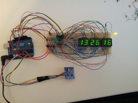
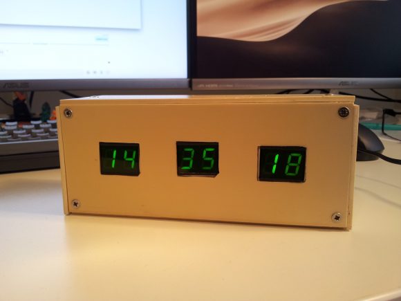
I had an arduino uno and some modules laying around for some time, and finally I decided to make it a weekend project and put it to useful work, by building a clock that could display the time in HH:MM:SS format.
Digging the web for inspiration, I found many examples that involved an extra 74HC595 shift register and a BCD to 7-segment decoder and a RTC (real time clock) module for greater accuracy.
I had a DS1307RTC module, the problem was that the only 7-segment decoder I found in the junkbox was a CD4511 which can only drive common-cathode dispays, and the displays I had where VQE24E common-anode.
I could’ve added transistors, but for 6 digits there would’ve been a lot of transistors and resistors.
In the end I found about SevSeg.h library, that makes it posibble to drive both common-cathode as well as common-anode displays easily, directly from arduino.
I took inspiration from here for the code: https://electronics-project-hub.com/arduino-7-segment-display-clock-with-and-without-rtc/
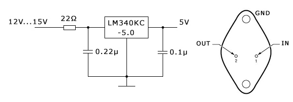
Below is my modified code and circuit diagram:
#include "SevSeg.h"
#include <Wire.h>
#include <TimeLib.h>
#include <DS1307RTC.h>
SevSeg Display;
const int ledPin =  A0;
unsigned long timeDisplay;
unsigned long currentMillis;
unsigned int Hour;
int ledState = LOW;
unsigned long previousMillis = 0;
const long interval = 500;
void setup()
{
  pinMode(ledPin, OUTPUT);
  byte numDigits = 6;
  byte digitPins[] = {10, 11, 12, 13, A1, A2};
  byte segmentPins[] = {2, 3, 4, 5, 6, 7, 8, 9};
  bool resistorsOnSegments = false; // false = resistors are on digit pins
  bool updateWithDelaysIn = true;
  byte hardwareConfig = COMMON_ANODE;
  Display.begin(hardwareConfig, numDigits, digitPins, segmentPins, resistorsOnSegments);
  Display.setBrightness(100);
}
void loop()
{
  unsigned long currentMillis = millis();
  if (currentMillis - previousMillis >= interval)
  {
    previousMillis = currentMillis;
    if (ledState == LOW)
    {
      ledState = HIGH;
    }
    else
    {
      ledState = LOW;
    }
    digitalWrite(ledPin, ledState);
  }
  tmElements_t tm;
  if (RTC.read(tm))
  {
    Hour = tm.Hour;
    if (tm.Hour == 0)
    {
      Hour = 24;
    }

    timeDisplay = (Hour * 100 + tm.Minute) * 100L + tm.Second;
  }
  else {
    timeDisplay = 888888; // error
  }
  Display.setNumber(timeDisplay);
  Display.refreshDisplay();
}
In the end I didn’t use the blinking seconds LED, but left the option there.

To set the time on the DS1307 RTC, I followed the instructions in the link above.
On the breadboard there are anode resistors, but I ended up not using them. These displays needed some higher current to lit up well during the day.
I know the box isn’t the prettiest one, but at least it’s a box :)
Later edit (12 june 2020):
It seems that the DS1307 RTC (at leas the one I have) is not so “real”… the clock gained over 60 seconds in almost three weeks. Not very accurate for a clock crystal.
