I had an arduino uno and some modules laying around for some time, and finally I decided to make it a weekend project and put it to useful work, by building a clock that could display the time in HH:MM:SS format.
Digging the web for inspiration, I found many examples that involved an extra 74HC595 shift register and a BCD to 7-segment decoder and a RTC (real time clock) module for greater accuracy.
I had a DS1307RTC module, the problem was that the only 7-segment decoder I found in the junkbox was a CD4511 which can only drive common-cathode dispays, and the displays I had where VQE24E common-anode.
I could’ve added transistors, but for 6 digits there would’ve been a lot of transistors and resistors.
In the end I found about SevSeg.h library, that makes it posibble to drive both common-cathode as well as common-anode displays easily, directly from arduino.
I took inspiration from here for the code: https://electronics-project-hub.com/arduino-7-segment-display-clock-with-and-without-rtc/
Below is my modified code and circuit diagram:
#include "SevSeg.h"
#include <Wire.h>
#include <TimeLib.h>
#include <DS1307RTC.h>
SevSeg Display;
const int ledPin =  A0;
unsigned long timeDisplay;
unsigned long currentMillis;
unsigned int Hour;
int ledState = LOW;
unsigned long previousMillis = 0;
const long interval = 500;
void setup()
{
  pinMode(ledPin, OUTPUT);
  byte numDigits = 6;
  byte digitPins[] = {10, 11, 12, 13, A1, A2};
  byte segmentPins[] = {2, 3, 4, 5, 6, 7, 8, 9};
  bool resistorsOnSegments = false; // false = resistors are on digit pins
  bool updateWithDelaysIn = true;
  byte hardwareConfig = COMMON_ANODE;
  Display.begin(hardwareConfig, numDigits, digitPins, segmentPins, resistorsOnSegments);
  Display.setBrightness(100);
}
void loop()
{
  unsigned long currentMillis = millis();
  if (currentMillis - previousMillis >= interval)
  {
    previousMillis = currentMillis;
    if (ledState == LOW)
    {
      ledState = HIGH;
    }
    else
    {
      ledState = LOW;
    }
    digitalWrite(ledPin, ledState);
  }
  tmElements_t tm;
  if (RTC.read(tm))
  {
    Hour = tm.Hour;
    if (tm.Hour == 0)
    {
      Hour = 24;
    }

    timeDisplay = (Hour * 100 + tm.Minute) * 100L + tm.Second;
  }
  else {
    timeDisplay = 888888; // error
  }
  Display.setNumber(timeDisplay);
  Display.refreshDisplay();
}
In the end I didn’t use the blinking seconds LED, but left the option there.

To set the time on the DS1307 RTC, I followed the instructions in the link above.
On the breadboard there are anode resistors, but I ended up not using them. These displays needed some higher current to lit up well during the day.
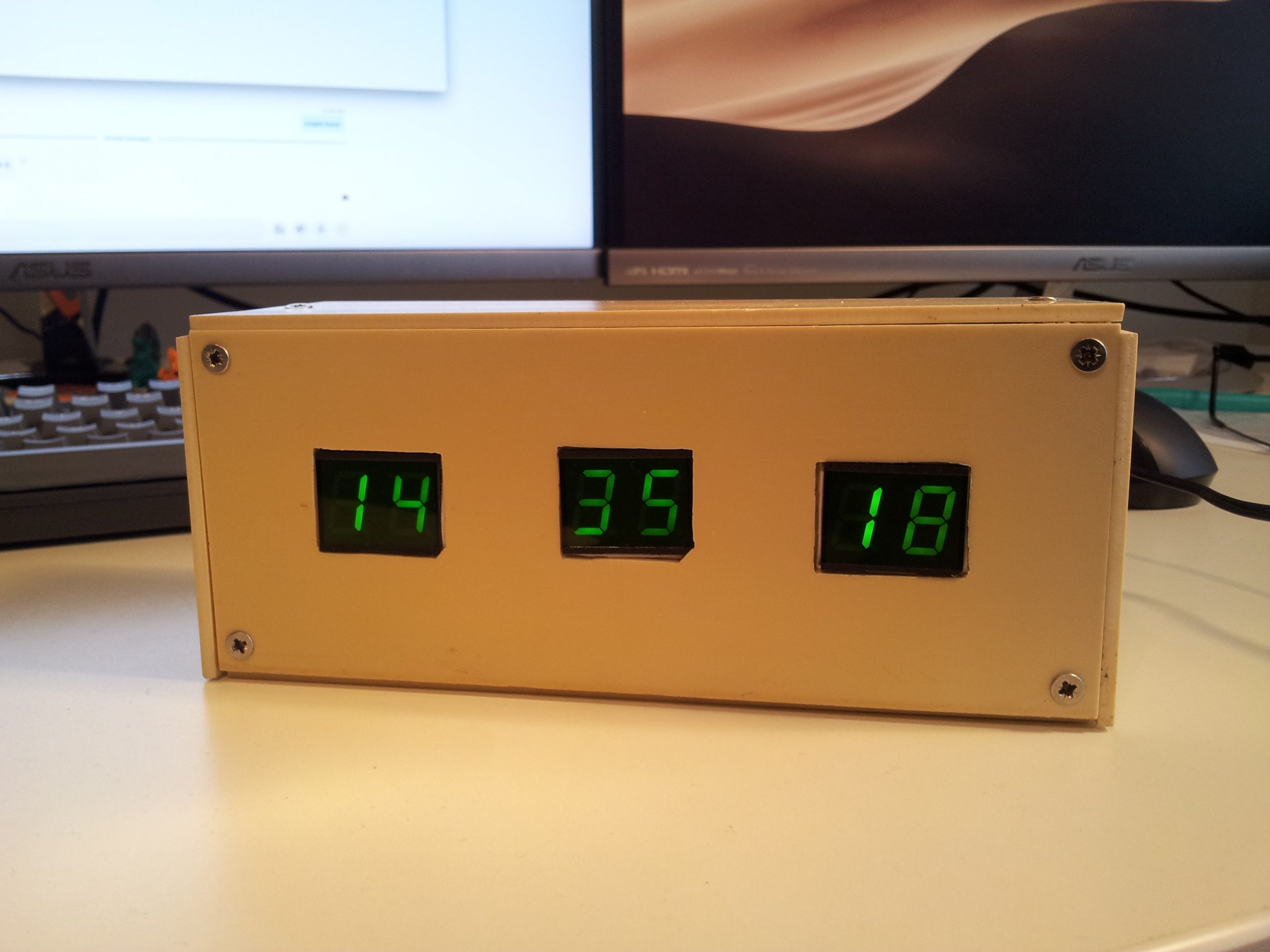
I know the box isn’t the prettiest one, but at least it’s a box :)
Later edit (12 june 2020):
It seems that the DS1307 RTC (at leas the one I have) is not so “real”… the clock gained over 60 seconds in almost three weeks. Not very accurate for a clock crystal.
Output one error
Hello!
For me it worked.
If it does not work for you, dig into it and debug. That is the fun part!
Good luck!
HI BUDDY. THIS IS EXACTLY WHAT I NEED. DO YOU HAVE A CODE WITH PUSH BUTTONS TO SET TIME. CAN I USE A DS3231 FOR THIS.
THANKS
MITCH MITCHELL
mitch@scotchandsofa.co.za
Hello!
Check the link to the article I’ve mentioned in the text. There is an example with push buttons also.
You can use any RTC, just include the appropriate library and change the code to read the RTC correctly.
Good luck!
Hi, your project is doing the right thing and I could make it. But I can not give any picture here. Clock would have run at 24 hours, but need 12 hours (AM / PM).
Thank you very much
Hello!
To achieve this you could replace the if statement (line 45 to 48, including those) with something like this:
if (tm.Hour > 12){
if (tm.Hour == 13) Hour = 1;
if (tm.Hour == 14) Hour = 2;
if (tm.Hour == 15) Hour = 3;
if (tm.Hour == 16) Hour = 4;
if (tm.Hour == 17) Hour = 5;
if (tm.Hour == 18) Hour = 6;
if (tm.Hour == 19) Hour = 7;
if (tm.Hour == 20) Hour = 8;
if (tm.Hour == 21) Hour = 9;
if (tm.Hour == 22) Hour = 10;
if (tm.Hour == 23) Hour = 11;
}
else
{
if (tm.Hour == 0) Hour = 12;
}
If you want an AM/PM LED, you could use the seconds indicator LED declared on A0, changing it’s purpose to indicate AM/PM, or declaring a new one on the remaining A3 pin.
If you discard the seconds indicator to re-use it as AM/PM, delete the lines 27 to 40, as they will no longer be necessary, and in the new if statement (described above), change the LED state according to which part of day is it. For example:
if (tm.Hour > 12){
if (tm.Hour == 13) Hour = 1;
if (tm.Hour == 14) Hour = 2;
if (tm.Hour == 15) Hour = 3;
if (tm.Hour == 16) Hour = 4;
if (tm.Hour == 17) Hour = 5;
if (tm.Hour == 18) Hour = 6;
if (tm.Hour == 19) Hour = 7;
if (tm.Hour == 20) Hour = 8;
if (tm.Hour == 21) Hour = 9;
if (tm.Hour == 22) Hour = 10;
if (tm.Hour == 23) Hour = 11;
ledState = HIGH; // PM
}
else
{
if (tm.Hour == 0) Hour = 12;
ledState = LOW; // AM
}
digitalWrite(ledPin, ledState);
Note that I have not tested this code.
Have fun!
The result of putting the current-limiting resistor in the digit line shows in the picture of the box where the “1” is brighter than the “4” and the “8” as fewer segments share the digit current. The “3” and the “5” in the middle are equally bright because the same number of segments are illuminated.
Actually, that is due to the “Display.setBrightness(100);” line.
“setBrightness” doesn’t really affect brightness, it controls the update rate of the digits.
100 = 2000µs delay after each digit
0 = 1µs delay
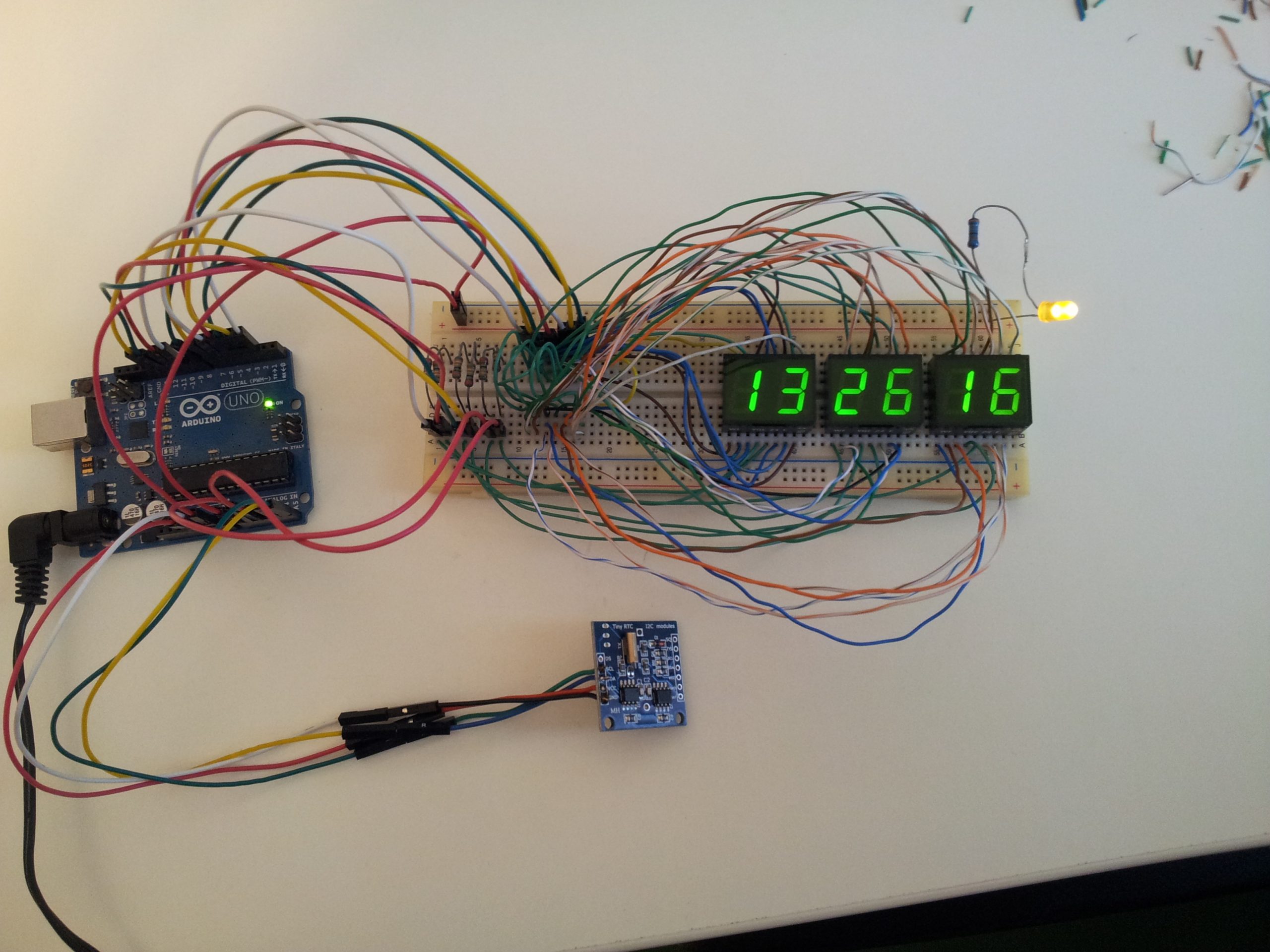
In the picture showing the breadboard, the “setBrightness” was set to 10, meaning the digits were updated faster than in the picture with the box where I’ve set it to 100.
The naked eye will not notice a difference between 10 and 100, but a camera will.
A slight difference in illumination can be seen in the breadboard picture also (the 1 and the 6 from seconds).
How to add switch?
How to add switch
What if I want to use bigger displays?
If the bigger displays need more that 1.2V and ~20mA (per segment), then you will need transistors to drive them.
Otherwise there is no problem.
I was wondering if i could use non addressable rgb led strips for each segment but i am wondering how would the schematic look like for that option. Some guidance would be much appreciated.
You could treat each stripe as a single LED, and connect seven of them to form a single 7 segment digit, as shown in this picture:
https://theorycircuit.com/wp-content/uploads/2018/02/7-segment-display-pinout-cc-ca.png
I have combined suggestions to make sketch that displays 12 hours, has PM indicator, and uses DS3231 RTC, but still can’t get the time setting buttons to work. Please help. Thanks.
Great project! Could this be done with 6 single digits, instead of 3 duo digits?
Yes. Same wires/pin connections. The double digits are just two single digits stuck togeter.
Very nice video ..How to add hour and minute switch..
where to change code.
please tell me Sir..
please sir…
Hello,,
I want project using Ds1302 to view clock on leds and relay